
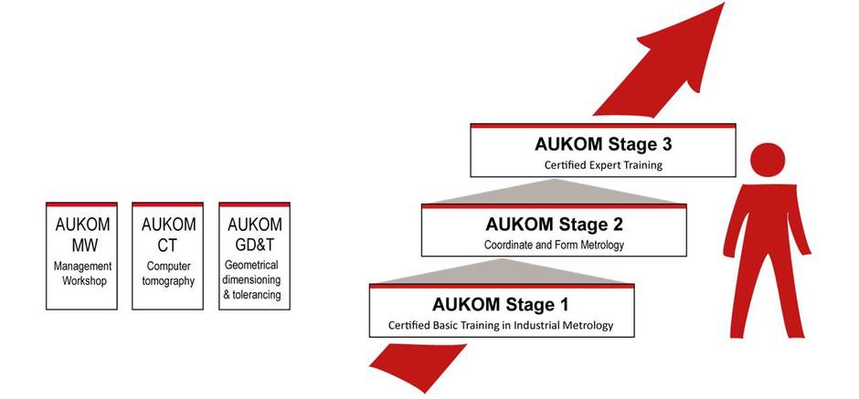
Learning a new software can be much like climbing a ladder where every step has to be done carefully. However, sometimes the steps are too far apart for some of us leading to wasted time and effort. This is where WENZEL’s training programs come into play. For example, rather than take all OpenDMIS or Quartis courses, a beginner student can first opt to take AUKOM Level 1 where they will learn the basics of metrology first. Then, they can step into their introductory OpenDMIS course, for example, and, after a couple of months, follow up with AUKOM Level 2.
Taking classes in this way ensures a wholesome learning experience where all of the gaps are filled in for the students because a myriad of broad topics are covered. If you’re wondering what we offer in the AUKOM classes that we can teach, find it below!
AUKOM Level 1
1-1 Units
SI Units, incl. Definition and History, Base Quantities, Derived Quantities, Prefixes of Units, Angles, Conversion Degrees <-> Radian, Conventional Measuring and Test Equipment
1-2 Coordinate Systems
(Mathematical) Drawing Plane, Origin, Cartesian Coordinates, Right-Hand Rule, Translation and Rotation, Polar Coordinates, Cylindrical and Spherical Coordinate System
1-3 Coordinate Measuring Machines
History of Coordinate measuring machines, Cantilever/Bridge/Column/Gantry Types, Differences in the Types, Axis Guide, Measuring Computer and Software, Work Holding Fixture, Accuracy of Coordinate Measuring Machines, CAA Correction, Form Measuring Machines
1-4 Sensors
Sensor selection, Stylus System, Stylus, optical sensors, Image Processing, Laser Triangulation
1-5 Basic definitions
Drawing Entries (Dimensions, Tolerance Symbols), Standard Reference, Differences Nominal Element – Real Element – Extracted Element – Associated Element, Free Form surfaces
1-6 Dimensional Tolerance
Dimensional Tolerances, Taylor’s Principle, Standards, Symbols and Drawing Entries, Length Dimensions, Angular Dimensions, Limiting Dimensions and Fits, ISO Fitting/Mating System, Common Tolerances
1-7 Geometric elements
Standard form elements: Plane/ Cylinder/ Cone/ Sphere/ Line/ Circle/ Point/ Ellipse, Vector, Normal Vector, Minimum Number of Points, Projection
1-8 Geometric constructions
Calculation of characteristics out of two geometrical features (distance, angle), Calculation of features out of two geometrical features (Intersection, Symmetry), Calculation of new features out of some geometrical features (Construction)
1-9 Preparing a Measurement on the Coordinate Measuring Machine
Standardized Temperature, Part Cleaning, Temperature Control, Fixturing, (Avoiding Distortion), Fixturing Systems, CMM and Software Startup
1-10 Stylus Selection and Qualification
Stylus System Selection, Stylus Qualification, Reference Sphere, Reference Stylus, Stylus Sphere Radius Correction, Stylus Tip Bending Correction, Mechanical Filter Effect of the Stylus, Errors of Incorrect Qualification,
1-11 Measuring using Coordinate Measuring Machines
Determining part Coordinate System, Difference to Control Coordinate System, Manual and automatic Alignment, Probing, References, Consequences of Collisions, Number of Probing Points and their Distribution, Influences on measuring result
1-12 Evaluation of Measurement and Statistics
Importance of Statistical Parameters, Outliers, Scattering, Histogram Representation, Compensation Methods, Influences on measuring result
1-13 Inspection planning
Completely defined characteristic, Purpose of the Measurement, Production of workpiece, Function of workspiece, Feature description, Manufacturing Methods and Accuracies, Shape Deviations, Uncertainty Effects, Awareness of Measuring Uncertainty, Inspection planning, Identifying measuring features
1-14 Documentation and Quality Management
Measurement Reports, Quality Control Charts, Cooperation between Design – Production – Testing, Reproducible and Clear Measurement Documentation, Measuring Strategy documentation

AUKOM Level 2
2-1 Overview of the Entire Measuring Process
Short repetition of the contents of stage 1
2-2 Geometric Overview
Standard Geometric Elements, Surface and Space Points, Punched Hole/Slot, Tetragonal/Hexagonal Hole, Symmetry, Perpendicular, Parallelism, Angle in Space, Coordinate System Transformations
2-3 Form and Positional Tolerances
Introduction to the Form and Positional Tolerances, Symbols and Drawing Entries, Form Tolerances, Reference Designation, Directional, Positional and Runout Tolerances, General Tolerances
2-4 Measuring Strategy
Define Clamping Setups and References (Practical Instructions), Order of Reference and Origin Selection, Iterative Alignment, Alignment According to the 3-2-1 and Best-Fit Methods (3-D Fit), Measuring Element and Auxiliary Elements, Machine Grid Measurements, Contour Measurements, Measurement with Cylinder Surfaces, etc.
2-5 Probing Strategy – Tactile
Number and Distribution of Probing Points, Probing Force and Speed, incl. Material Properties, Stylus Diameter, Special Styli, Scanning
2-6 Probing Strategy – Image Processing
Single-shot measurement, Multi-shot measurement, Edge finder, Contour image processing, Projection optics, Illumination, Filter, Scanning, Auto focus
2-7 Probing Strategy – Distance Sensors
Laser triangulation sensors, Foucault sensor, White light sensor, Light section sensor, Photogrammetry, Fringe protection, Influence on the measuring results
2-8 CNC Programming
Teach-In, Offline Programming, Measuring against CAD Data, Clarity and Self-Explanatoriness of Variables, Modules and Programs
2-9 Measurement of Free Form Surfaces
Element types in Free Form Surface Metrology? Effect of a 3D-Fit, Different Measuring Strategies, Programming Methods for Establishing Measurement Sequences
2-10 Evaluation
Evaluation Criteria: Function-oriented and Manufacturing-oriented Evaluation Methods, Differences in the Association Methods (Gauss, Envelope, Minimum Requirement), Constructions, Graphic and Tabular Evaluation, Measurement Logs
2-11 Effects on the Measurement Result
Effects on the Measurement Result, Reduction of Measurement Uncertainty, Detection and Reduction of Systematic and Random Effects, Temperature Compensation
2-12 Documentation
Principles of Documented and Reproducible Documentation, Graphic Evaluation, Form Plots, Measurement Reports and Their Improvement
2-13 Test Equipment Monitoring
Test Equipment Monitoring, incl. Monitoring Strategies, Test Specimen, normals, Monitoring and Acceptance Test of Coordinate Measuring Machines, Qualification Chain
2-14 Good Measurement Practice
Good Measurement Practice, Necessity of Cooperation

AUKOM Level 3
3-1 Basic Knowledge – Geometry
Calculation of Angle, Center of Gravity, Distance, Area
3-2 Basic Knowledge – Production Technology
Production Types and Achievable Production Precisions, Shape Deviations and Their Causes, Functionally Adequate Design and Construction Suitable for Production
3-3 Basic Knowledge – CAD
Principles of Construction and Technical Drawing, Principles and Tools of CAD Design, Imaging of Geometry, Model Types, CAD Data Dimensions, CAD Formats, Import of CAD Data, Interfaces
3-4 Point Cloud and Computer Tomography
Development of computer tomography technology, Physical principle, From the radiographic image to the measure, Tomography “on the image”, Region of interest, Initial sampling of the entire component, Evaluations of the deviations from the nominal geometry, Measurement of sections, Checking the material structure, Radiation spectrum, Beam hardening, Scattered radiation, Cone beam artifact, Noise, Further applications; Additionally: Fringe Projection, Photogrammetry, Tracking
3-5 Creation of Measurement Programs
Precision-Optimized Measuring Sequence, Time-Optimized Measuring Sequence, Travel Path Optimization, Feature-Oriented Measuring, Remote Programming, Safety Points and Planes, Program Loops / Branches/ Modules, Macros, User Interfaces, Program Optimization Loops, If/Then Conditions, DMIS Standard
3-6 Digital Filtering and Evaluation
Software Filters, Gauss Filters, High-Pass, Low-Pass, Waviness, Roughness, Comparison Form Tester – CMM
3-7 Monitoring of CMMs
CMM Monitoring, ISO 10360/VDI 2617, Possibilities to optimize the accuracy of CMMs, Examples, Experience
3-8 Measuring Uncertainty and Measuring Process Suitability
GUM Handbook, Determination of the Measuring Uncertainty, Uncertainty Budgets, PUMA Method, Increasing Measurement Uncertainty, Extended Measurement Uncertainty, Conformity, ISO 14253, Determination of Uncertainty Using Calibrated parts, Use of the Virtual CMM, Measuring Process Suitability according to MSA (GR&R), VDA 5, Comparing the methods
3-9 Quality Management
Quality Management Systems, Quality Management Handbooks, Quality Management Standards, Audit and Certification, Quality Tools, Fixed and Actual Costs, Origin of Errors and Error Elimination, Cost-Conscious Tolerance
3-10 Process Monitoring
Process Monitoring, Statistical Process Control (SPC), cp Values, cpk Values, cm Values, cmk Values, Monitoring Strategies and Quality Control Cards
3-11 Aspects of Measuring Room Management
Measured Data Management, Measuring Room Management, User Qualification, Training Plans and Options for Metrologists
AUKOM GD&T
GD&T-1 Basic rules of the ISO system of GPS-System
Introduction, ISO 8015 – Basic rules of the Geometrical Product Specification (GPS), Steps to check geometrical deviations, Extracted median line – extracted median surface.
GD&T-2 Tolerances of form, orientation, location and run-out – drawing indications.
Drawing symbols to indicate form, orientation, location and run-out tolerances, Tolerance zones, Default rules of indications and examples to indicate exceptions.
GD&T-3 Tolerances of form
Straightness, Roundness, Flatness, Cylindricity, Measuring of form deviations
GD&T-4 Tolerances of orientation, location and run-out
Relation between form deviations and orientation, location, run-out deviations, Datum referencing, Orientation, Location, Run-out
GD&T-5 Tolerances of profile form
Definitions, Drawing indications, Examples
GD&T-6 Principles of tolerancing I
Definition of sizes – ISO and ASME, Principle of independence, Envelope requirement, Summary and examples
GD&T-7 Principles of tolerancing II
Basic rules of drawing indication, MMR – Maximum Material Requirement, Tolerancing of form and perpendicular deviations using MMR, Tolerancing of positional deviations using MMR, Checking workpieces considering MMR, Tolerancing of coaxial deviations using MMR, Tolerancing of symmetry deviations using MMR, LMR – Least Material Requirement, Reciprocity requirement
GD&T-8 Tolerances of form, orientation, location and run-out – ASME
Basic rules and definitions, Envelope requirement, Datum referencing, Form tolerances, Orientation tolerances, Location tolerances, Composite and multiple-single-segment position tolerances, Profile form tolerances
GD&T-9 Workshop
Overview about the use of association criteria (Default rules), Additional tolerancing indications in future (Deviations of the default rules), Examples to filtering, straightness tolerancing and datum referencing, Positional tolerancing (Without and with maximum material requirement), Symmetry tolerancing (Maximum material requirement), Maximum material requirement – Simulation of Go-gauging, Maximum material requirement – Comparison of optimization criteria.
I hope this outline helps give you an idea of some of the material we have to offer here at WENZEL that will benefit your manufacturing process to the best of its abilities. Should you have more questions about our training programs, please don’t hesitate to contact us or visit our website at www.wenzelamerica.com. Also, don’t forget to follow us on LinkedIn for more metrology related news!