
The development of the very first CMM Coordinate Measuring Machine.
Research shows the development of modern 3-axis machines started in the early 1960s as direct descendants of modern 2-axis metrology machines invented in the 50s in various military defense industries.
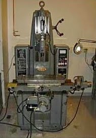
The very first 2-Axis universal measuring machine is believed to have been developed by the Sheffield Corporation in the mid to late 1940s. The YZ Machine, as it was called, was used to measure the shells of Hydrogen bombs at a national laboratory in Oak Ridge, Tennessee. The top secret nature of this project leaves us with little actual data about the machine though. Then in 1957, the Moore Tool Company of the United States introduced the Moore No. 3 Universal CMM Coordinate Measuring Machine aka the M3.
Digital Electronic Automation of Italy and Ferranti of Scotland, both developed 3-Axis coordinate measuring machines. The very first three-axis prototypes arrived during the 1960s and are invented by the Italian company DEA (now part of the Hexagon Metrology Group). That being said, the first working CMM was developed and put on sale by Browne& Sharpe in Melbourne, England. The DEA machine was a Portal Frame CMM with Hard Probe. While, Ferranti Metrology’s machine was a Cantilever CMM with Digital Read Out and Fixed Probes.
LK Tool, also from the UK, have long claimed to produce the first Bridge CMM that has become the standard configuration for modern Coordinate Measuring Machines. The various types of configuration that have been developed since, include the Cantilever CMM, Bridge CMM, Gantry CMM, Horizontal Arm CMM, Portal CMM, Moving Table CMM, Fixed Bridge CMM and Articulated Arm CMM. Decades later the Metrology industry today, amid the COVID-19 crisis, the global market for Coordinate Measuring Machines estimated at US$2.8 Billion in 2020.
CMMs come either as a Manual CMM, where the CMM Operator manually guides the CMM around the part to do the measuring or as a CNC/DCC CMM where the CMM is driven automatically from a computer controlled program. One thing we know for sure is that the innovation in metrology has been non-stop ever since, and used in every modern industrialized country. The metrology industry and advanced measuring machine capabilities has helped manufacturers improve and create all of the products we have today. CMMs are used for monitoring high-paced production and in-depth investigation as well as reverse engineering of various parts like turbine blades, car body parts, engine parts, gears, antennae, boat parts, and medical implants. Automotive, aerospace and defense are key industries for the CMM market with huge potential in medical device development. Regionally, Europe is the biggest consumption area of Coordinate Measuring Machine in the world and China has the most potential market with the fastest growing rate of 16.19%.
Modern Measuring Machine Developments.
The following is excerpted and paraphrased from Wikipedia per Creative Commons Copyright. In modern machines, the gantry type superstructure has two legs and is often called a bridge. This moves freely along the granite table with one leg (often referred to as the inside leg) following a guide rail attached to one side of the granite table. The opposite leg (often outside leg) simply rests on the granite table following the vertical surface contour. Air bearings are the chosen method for ensuring friction free travel.
In these, compressed air is forced through a series of very small holes in a flat bearing surface to provide a smooth but controlled air cushion on which the CMM can move in a frictionless manner. The movement of the bridge or gantry along the granite table forms one axis of the XY plane. The bridge of the gantry contains a carriage which traverses between the inside and outside legs and forms the other X or Y horizontal axis. The third axis of movement (Z axis) is provided by the addition of a vertical quill or spindle which moves up and down through the center of the carriage. The touch probe forms the sensing device on the end of the quill.
The movement of the X, Y and Z axes fully describes the measuring envelope. Optional rotary tables can be used to enhance the approachability of the measuring probe to complicated workpieces. The rotary table as a fourth drive axis does not enhance the measuring dimensions, which remain 3D, but it does provide a degree of flexibility. Some touch probes are themselves powered rotary devices with the probe tip able to swivel vertically through 90 degrees and through a full 360 degree rotation.
As well as the traditional three axis machines (as pictured above), CMMs are now also available in a variety of other forms. These include CMM arms that use angular measurements taken at the joints of the arm to calculate the position of the stylus tip. Such arm CMMs are often used where their portability is an advantage over traditional fixed bed CMMs. Because CMM arms imitate the flexibility of a human arm they are also often able to reach the insides of complex parts that could not be probed using a standard three axis machine.
Mechanical probes.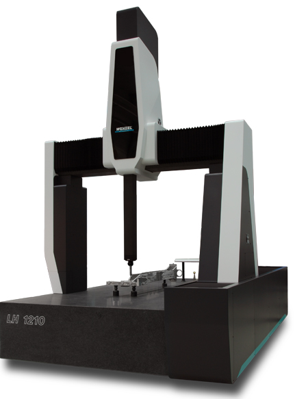
In the early days of CMM coordinate measuring machines, mechanical probes were fitted into a special holder on the end of the quill. A very common probe was made by soldering a hard ball to the end of a shaft. This was ideal for measuring a whole range of flat, cylindrical or spherical surfaces. Other probes were ground to specific shapes, for example a quadrant, to enable measurement of special features. These probes were physically held against the workpiece with the position in space being read from a 3-Axis digital readout (DRO) or, in more advanced systems, being logged into a computer by means of a footswitch or similar device.
Measurements taken by this contact method were often unreliable as machines were moved by hand and each machine operator applied different amounts of pressure on the probe or adopted differing techniques for the measurement. A further development was the addition of motors for driving each axis. Operators no longer had to physically touch the machine but could drive each axis using joysticks in much the same way as with modern remote controlled cars. Measurement accuracy and precision improved dramatically with the invention of the electronic touch trigger probe. The pioneer of this new probe device was David McMurtry who subsequently formed what is now Renishaw plc.
[2] Although still a contact device, the probe had a spring-loaded steel ball (later ruby ball) stylus. As the probe touched the surface of the component the stylus deflected and simultaneously sent the X.Y,Z coordinate information to the computer. Measurement errors caused by individual operators became fewer and the stage was set for the introduction of CNC operations or Direct Computer Controlled and the coming of age of DCC CMMs.
Non-Contact probes
Optical probes are lens-CCD-systems, which are moved like the mechanical ones, and are aimed at the point of interest, instead of touching the material. The captured image of the surface will be enclosed in the borders of a measuring window, until the residue is adequate to contrast between black and white zones. The dividing curve can be calculated to a point, which is the wanted measuring point in space. The horizontal information on the CCD is 2D (XY) and the vertical position is the position of the complete probing system on the stand Z-drive (or other device component).
This allows entire 3D-probing.New Probing Systems. There are newer models that have probes that drag along the surface of the part taking points at specified intervals, known as CORE. This method of CMM coordinate measuring machine inspection is often more accurate than the conventional touch-probe method and most times faster as well. The next generation of scanning, known as non-contact scanning includes high speed laser single point triangulation,[3] laser line scanning,[4] and white light scanning,[5] is advancing very quickly.
This method uses either laser beams or white light that are projected against the surface of the part. Many thousands of points can then be taken and used to not only check size and position, but to create a 3D image of the part as well. This “point-cloud data” can then be transferred to CAD software to create a working 3D model of the part. These optical scanners often used on soft or delicate parts or to facilitate reverse engineering.
WENZEL America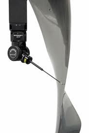
WENZEL America incorporates many of these traditional CMM technologies and continues with intrinsically stable, hand lathed granite foundations within its measuring machine designs. Sourcing and innovating the ideal metrological material, granite, coupled with the Renishaw 5-Axis and other advanced probing is proving to be the path of accuracy.
To learn more about WENZEL America’s CMM coordinate measuring machines including advanced Computed Tomography, non-contact and 3D scanning as well as the most advanced Renishaw REVO systems built on the rock-solid WENZEL CMMs visit our website or give us a call. Our goal is to solve every measurement problem you have. Put us to the test. (Updated 30 April 2021)