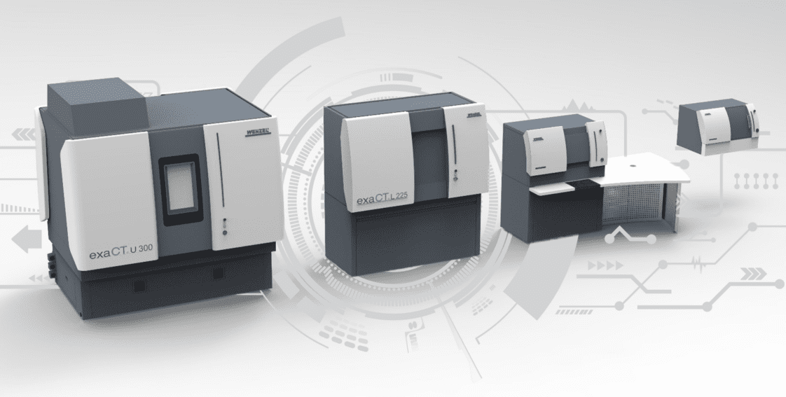
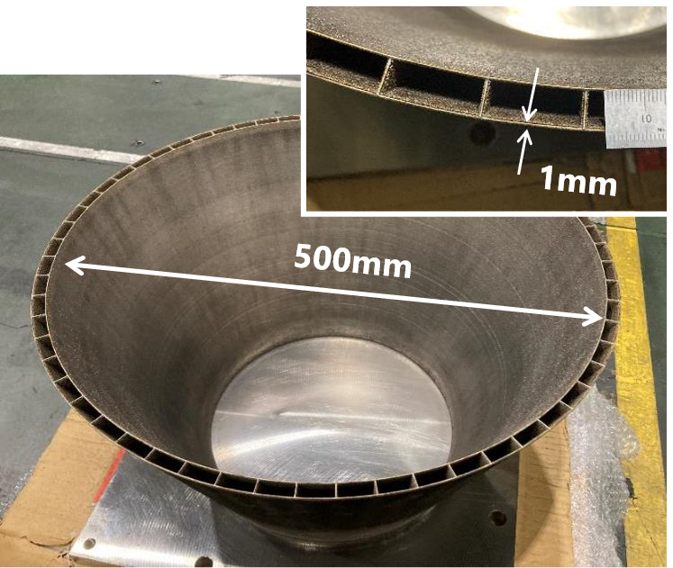
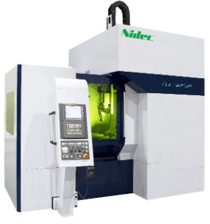
WENZEL America and NIDEC continue their collaboration exploring how the exaCT U computed tomography machine from WENZEL can open a world of information into Directed Energy Deposition (DED) Additive Manufacturing by NIDEC Machine Tool America’s LAMDA system. A powerful 3D manufacturing system with the latest technology that processes some of the toughest metals.
Additive manufacturing first emerged in 1987 in Japan and since then there have been many new applications branching out into several different types of technologies turning CAD files into 3D physical objects right across the world. Even highly complex objects and shapes can be fabricated and have already been accepted and used in many industries. In this article, we will explore one such technology, Directed Energy Deposition (DED), and the ability to ensure the product’s quality that comes from it.
Introduction to DED additive manufacturing process
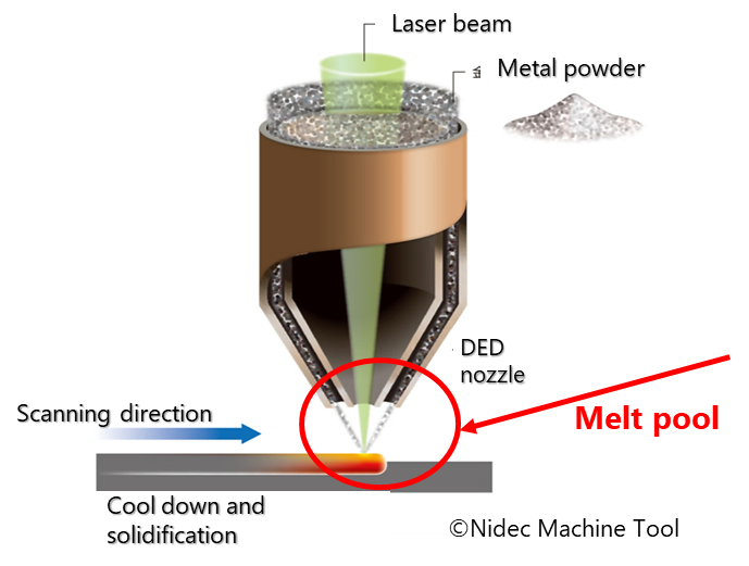
Laser powder-directed energy deposition (LP-DED) is a powerful additive manufacturing (AM) technique that utilizes a focused laser beam to melt and fuse metal powder layer-by-layer, building a desired 3D object. A nozzle feeds the metal powder into the molten pool created by the laser, enabling precise material placement and intricate design features
Compared to other AM processes like powder bed fusion, LP-DED offers greater flexibility as it can work directly on existing components. This makes it ideal for repairs, adding features to existing parts, and creating functionally graded structures where material properties vary throughout the object. Additionally, LP-DED can handle a wider range of materials, including metals that are difficult to process with other methods
A Major Advantage
A significant advantage of NIDEC’s LAMDA LP-DED is the ability to perform large-scale metal additive manufacturing without the need for a full environmental chamber. This is achieved by using a local shield, which is a gas enclosure focused around the deposition area. The local shield minimizes the interaction of the laser and powder with the surrounding environment, mitigating concerns about fumes, spatter, and oxidation. This not only simplifies the setup but also reduces costs and energy consumption compared to chamber-based AM systems.
An significant advantage of NIDEC’s LAMDA LP-DED is the ability to perform large-scale metal additive manufacturing without the need for a full environmental chamber. This is achieved by using a local shield, which is a gas enclosure focused around the deposition area. The local shield minimizes the interaction of the laser and powder with the surrounding environment, mitigating concerns about fumes, spatter, and oxidation. This not only simplifies the setup but also reduces costs and energy consumption compared to chamber-based AM systems.
A significant advancement is NIDEC’s use of monitoring and real-time feedback to control the process. Combined with AI and machine learning, LAMDA systems can detect various abnormalities and stop the process automatically, before the build is harmed.
The combination of material versatility, repair capabilities, and the ability to perform large-scale manufacturing makes LP-DED a valuable tool for various industries, including aerospace, automotive, and energy. As research and development continue to improve process control and material understanding, LP-DED is expected to play an even more significant role in the future of additive manufacturing.
CT scanning technology and its capabilities in non-destructive testing
The Industrial Computed Tomography (CT), an advanced non-destructive testing method, provides detailed internal views of parts, even penetrating metal and plastic. Paired with the right software the industrial CT goes even further and scanned data becomes a comprehensive engineering and metrology tool. CT technology has existed for decades, offering swift inspections, revealing internal structures that traditional metrology methods lack, and improving cost efficiency and productivity. Unlike other machines, CT scanning offers deep analysis of internal structures, material structures and potential failure points.
Quality Control and combining CT scanning with DED
CT systems are an invaluable tool in the world of materials testing, offering a unique way to uncover hidden features within metals. In the case of DED, it would be critical to know the quality when adding features to existing parts, or when you create functionally graded structures where material properties vary throughout the object. These systems work by accurately measuring the density of the material, which can provide insights into its strength and durability. Additionally, CT systems can identify the presence of pores, which can affect the material’s performance. In other instances, they can also pinpoint cracks, even those not visible to the naked eye, which could potentially lead to catastrophic failure in the product.
Another critical application of these systems is in checking the dimensional accuracy of a build, ensuring that it meets the specified measurements and tolerances. This capability is essential in industries where precision is paramount. This can be achieved by performing a nominal/ actual comparison. In other words, we can load the CAD drawing of the part and compare it to the actual CT scan of the same part. In some cases, when CAD data is not available, we can compare a nominal part’s scan data with the scan data of the actual part.
Measuring Defects with CT Scanning in DED
The most common defects found in DED are porosity and cracks.. These defects can arise from impurities trapped within the component during the AM process. Analyzing the DED process reveals potential defects such as flash formation, voids, cracks, porosity, surface lines, and elevated surface roughness. Regardless of whether it is the PBF process or the DED process, deposition defects pose significant challenges. Addressing these defects constitutes a complex and demanding task. Luckily, with the latest CT technology software, measuring and detecting defects could give us insights into the correcting what is necessary to achieve the highest quality products.
Porosity also called Voids
Distinct types of porosity or voids are a frequent problem in additive manufactured cast, and molded parts. It occurs when a pocket forms due to air or gas trapped in the metal during solidification. The other reason for porosity is caused when the metal shrinks leaving voids in the center of the metal, called shrink porosity. Because the porosity is made up of air, it can be seen as lower density spots when scanned with a Computed Tomography machine making detection quite simple.
To accurately gauge porosity through density variations, appropriate software is crucial. WM Point Master by WENZEL is a CT analysis tool that identifies porosities with a simple click. It allows the quality assurance engineer to easily measure and visualize the porosity’s size, shape, and potential clusters. The operator can set a range for porosity sizes, color-coding them for easy identification and preventing the detection of overly small porosities. CT is particularly effective in detecting enclosed porosities within printed parts. Porosity types include thorough porosity, extending throughout the part, and blind porosity, characteristic of a defect on one part surface. Porosity detection should target machined areas and other critical high-stress sections.
The truth is, that there are limitations to CT scanning when detecting small pores.
The CT System will have limitations in resolution and penetration power. Selection of the X-ray tube and detector as well as the coordinate manipulator of the object within the scan envelope will determine the maximum magnification and resolution. Some CT systems will provide scan field extensions to allow multiple fields to be stitched together thus provideing a larger scan envelope. The resolution is also determined by the accuracy of the rotating table by providing the slice thickness.
“The voxel size (v) of a tomographic reconstruction can be determined as v = p M , (1) using the detector pixel pitch (p), and cone-beam magnification (M), the ratio of SOD and SDD. Besides deviations in the estimates of these two parameters, the true value of v is affected by X-ray source drift, thermal expansion of CT components, detector and stage tilt, and more [2].”
10th Conference on Industrial Computed Tomography, Wels, Austria (iCT 2020), www.ict-conference.com/2020
We should be able to see and measure with a high level of confidence 21µ to 26µ voids, occlusions, and cracks. If the angle is just right, we may detect it even better. When we measure from edges, we want to see that the transition in density is not more than three pixels. The level of sharpness of an edge should be around 3 or 4 pixels.
Cracks and internal fissures
Looking at why cracking occurs and during what part of the manufacturing process could be extraordinarily complex. Finding the crack and looking at how it migrates through the object could help guide you to an overall solution.
High-resolution CT such as the exaCT system is required in most cases to identify cracks in printed parts. Cracks are non-uniform and can traverse multiple directions in a particular part. It is important to identify cracks that are manifested through uneven cooling of a particular part during its manufacturing process. The cracks, like porosity can be identified and can be colorized using WM Pont Master software to study the materials characteristics and manufacturing process. CT is especially helpful in determining crack migration on parts that have been tensile tested.
A notable example of the usefulness of CT to study crack migration would be ballistics tests on body armor. It has been shown that layered polyurethane laminates can be studied after a ballistic test showing how the layers of polyurethane separate but maintain overall integrity to stop the projectile whether it is a bullet shape or shrapnel fragments.
WN Point Master can provide sub-voxel measurements of CT scans to compare shape, force, and its destructive effect on the materials.
Internal geometry deviations
CT scanning will provide internal and external surface data in the most complex parts.
For instance, after the demolding of plastic parts, a deformation occurs due to shrinkage and distortion of the plastic component. This deformation is usually compensated for in the injection mold by the shaping, so that the plastic part is first shaped into a “wrong” shape. After the plastic has cooled down, the component is then deformed back into the desired shape due to shrinkage and distortion to correspond as closely as possible to the nominal shape.
The traditional compensation of the tool geometry is carried out by iterative post-processing (milling, grinding, or eroding) of a new or existing tool shape. This post-processing is associated with immense effort and leads to the fact that the mold insert can often no longer be used.
In virtual deformation, the deformation specifications are derived from simulation systems or measurement results of actual scanned components. This enables WM | Point Master to calculate the deformation result fully automatically. Factors such as local volumes, shrinkage and the experience of toolmakers are considered. The fully automatic calculated distortion-compensated geometry is then converted into CAD surface models using the powerful reverse engineering functionality of WM | Point Master and WM | Quartis entered the existing tool data.
Computed Tomography detects variations in materials
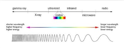
X-rays from CT Scanning are a form of electromagnetic radiation. Simply put, because X-rays have a shorter wavelength than light, they can penetrate materials. The material and the wavelength of the x-ray beam will determine how much of the beam is absorbed. There are different coefficients used to describe radiation in materials. For more information concerning this look at these sites:
Absorption Coefficient | PVEducation
Mass attenuation coefficient | Wikipedia
Linear attenuation coefficient | Radiopaedia
Radiology Reference Article | NIST Physical Measurment Laboratory
LET’S MEET IN LOS ANGELES!
Get ready, Los Angeles! NIDEC and WENZEL are heading your way for the largest and most influential additive manufacturing conference in North America – RAPID + TCT! Mark your calendars for June 25th through 27th June and stop by the Los Angeles Convention Center, 1201 S Figueroa St. Don’t miss out!
Visit NIDEC Machine Tool America at booth #847 and see how our high-accuracy laser powder-directed energy deposition technology can revolutionize your production process. We’ll be showcasing large-scale printing capabilities that eliminate the need for inert gas chambers, alongside real-time monitoring and feedback systems for complete control.
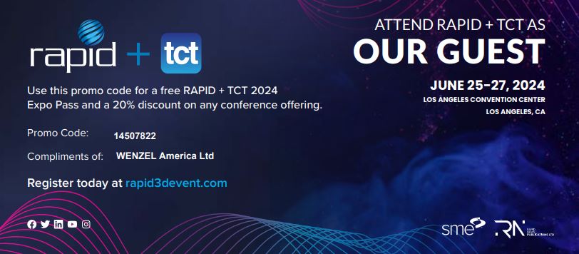
We also invite you to WENZEL’s booth, #1210. We will be exhibiting our WENZEL exaCT S, and proudly showcasing our PointMaster Software, a true innovation you don’t want to miss.