What is a Turbine?
- Different Types of Turbines
- About Axial Turbines & Compressors
- Both Worlds Combined – Gas Turbines
- The Structure of the Blade
- Measurement Drives Efficiency
- WENZEL Measures #morepartsfaster
Last week in All About Blades Part 1 we looked at the history of turbine blades in particular to breakthroughs and history makers. This week we will focus on what is a turbine, how they work, and what differentiates them.
A Turbine is a machine that produces continuous power in which a wheel or rotor, typically fitted with vanes, is made to revolve by a fast-moving flow of water, steam, gas, wind, or other fluid. Examples like the Hoover dam or the mighty Niagara Falls where the water runs through turbines that spin under the pressing force of the falling water and generates close to 4.9 million kilowatts to power 3.8 million homes. Did you know that Germany has 7,254 hydropower plants as of 2020? Or the famous old windmills in Holland that is the forerunners of today’s wind turbines that is an effective and low-cost source of renewable energy to generate electricity.

Different Types of Turbines
Turbo machines in mechanical engineering, describe machines that transfer energy between a rotor and a fluid or steam, including both turbines and compressors and are commonly used for automotive (turbo charger), aerospace (aircraft turbines), energy (gas and steam turbines), and industrial (compressors) applications.
Turbines can be divided by flow direction. The three primary areas are radial, diagonal, and axial and the flow medium determines what kind of turbine it would be. The four main types are steam, gas, water, and wind. All turbines are important and play major roles in the industry, but we will only be focusing on steam and gas which will lead us to look at axial and radial flow direction.
What is the difference between axial and radial turbines? With a radial turbine, the flow is smoothly orientated perpendicular to the rotation axis, and it drives the turbine in the same way water drives a watermill. The result is less mechanical stress (and less thermal stress, in case of hot working fluids) which enables a radial turbine to be simpler, more robust, and more efficient (in a similar power range) when compared to axial turbines. With the axial turbine the flow of the working fluid is parallel to the shaft axial compressor, converting flow of the fluid into rotating mechanical energy.
All turbines are important, but it is the jet turbine’s complex profile
that we love to measure
More about axial turbines and compressors
#allaboutblades will in essence be, all about turbine blades and therefore we want to focus on axial turbo machines!
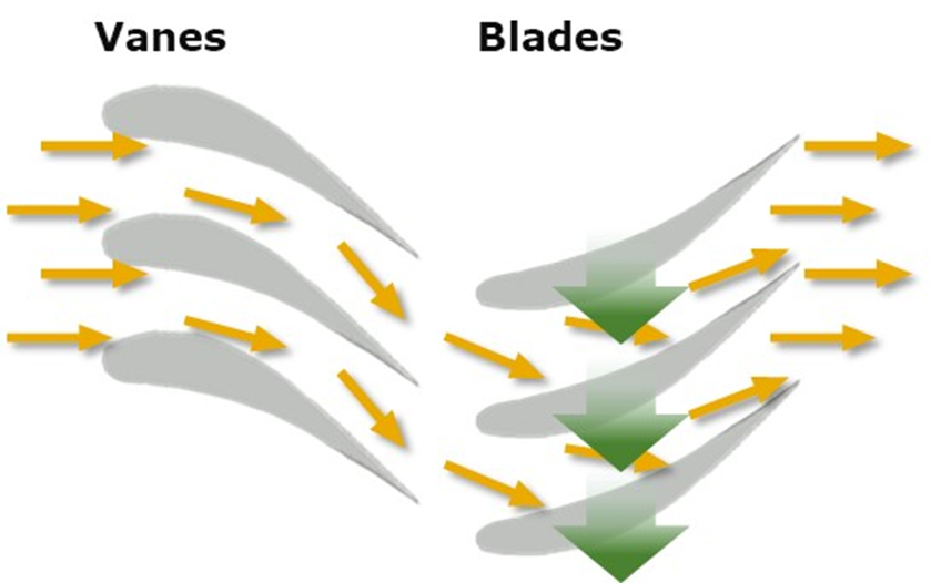
Axial turbines and compressors consist of multiple stages. Stages are the combination of a pair of rotating and stationary blades (vanes). Blades are connected to the rotor; vanes are connected to the casting. The main function of blades is to ensure the energy transfer between the gas and the rotor. Vanes on the other hand prepare the gas for entering the next set of rotating blades and redirect the flow of the passing gas from the previous set of blades to the next set of blades. This results in a guided flow of compressed air, high energy steam or exhaust gas through the turbine/compressor to transfer the highest possible amount of energy.
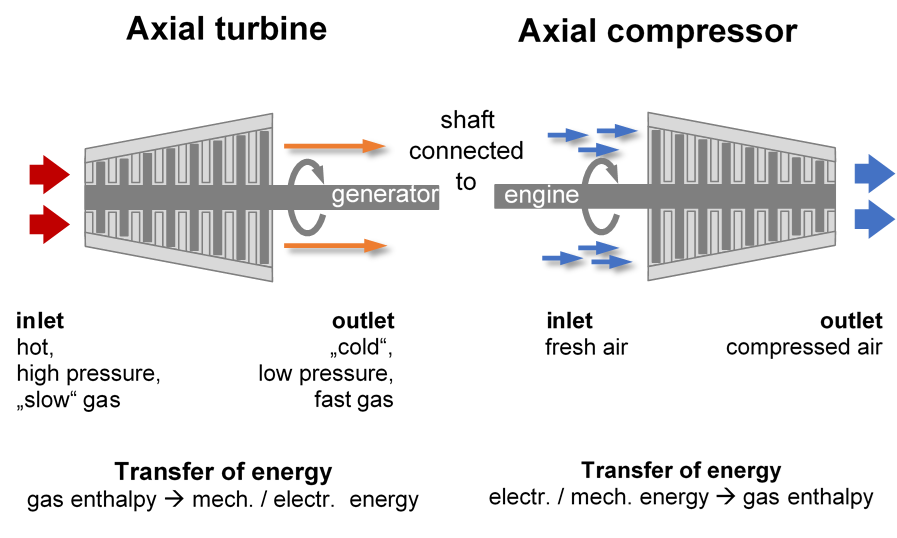
Axial turbines and compressors are different kind of turbo machines sharing the same basic principles, just in a reversed way.
Turbines get fed with high energy gas, that passes through the turbine. Stage by stage it transfers its energy to the blades. The passing gas relaxes, expands and therefore the blades and vanes increase in size along the axial flow path of the gas. In the end all the energy is transferred to the blades and therefore rotor to finally drive another machine. In the case of energy generation in power plants the turbine is connected to a generator to produce current.
A compressor works in a reversed way and is driven by an engine. As the air gets sucked in by the rotating blades it is pushed through the compressor. Each set of blades/vanes is slightly smaller, adding more energy and compression to the air.
Both worlds combined – Gas turbines
Aircraft turbines have a compressor as well as a turbine and in between you can find the combustion chamber. Air gets sucked into the turbine, compressed, and mixed with fuel for combustion that would result in thrust. In addition, a turbine in the exhaust stream is activated by the exhaust gas flow. The rotor of the turbine is connected to the compressor and therefore works as via a mechanical connection engine to the compressor that drives the compressor. But the main energy of the hot exhaust is used to produce thrust by increasing its velocity through the nozzle.
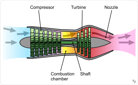
This basic principle can be found in turbojet / jet engines, that are the simplest types of aircraft gas turbines.
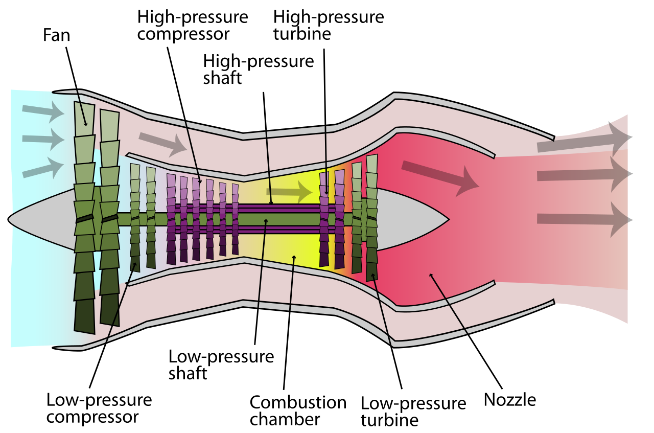
The turbofan gas turbine is the most common type of turbine engine found on airline jets today. The basic principle is the same, but the components are more complex. In addition, you can find a fan and a bypass system to further increase efficiency and stability of the turbine.
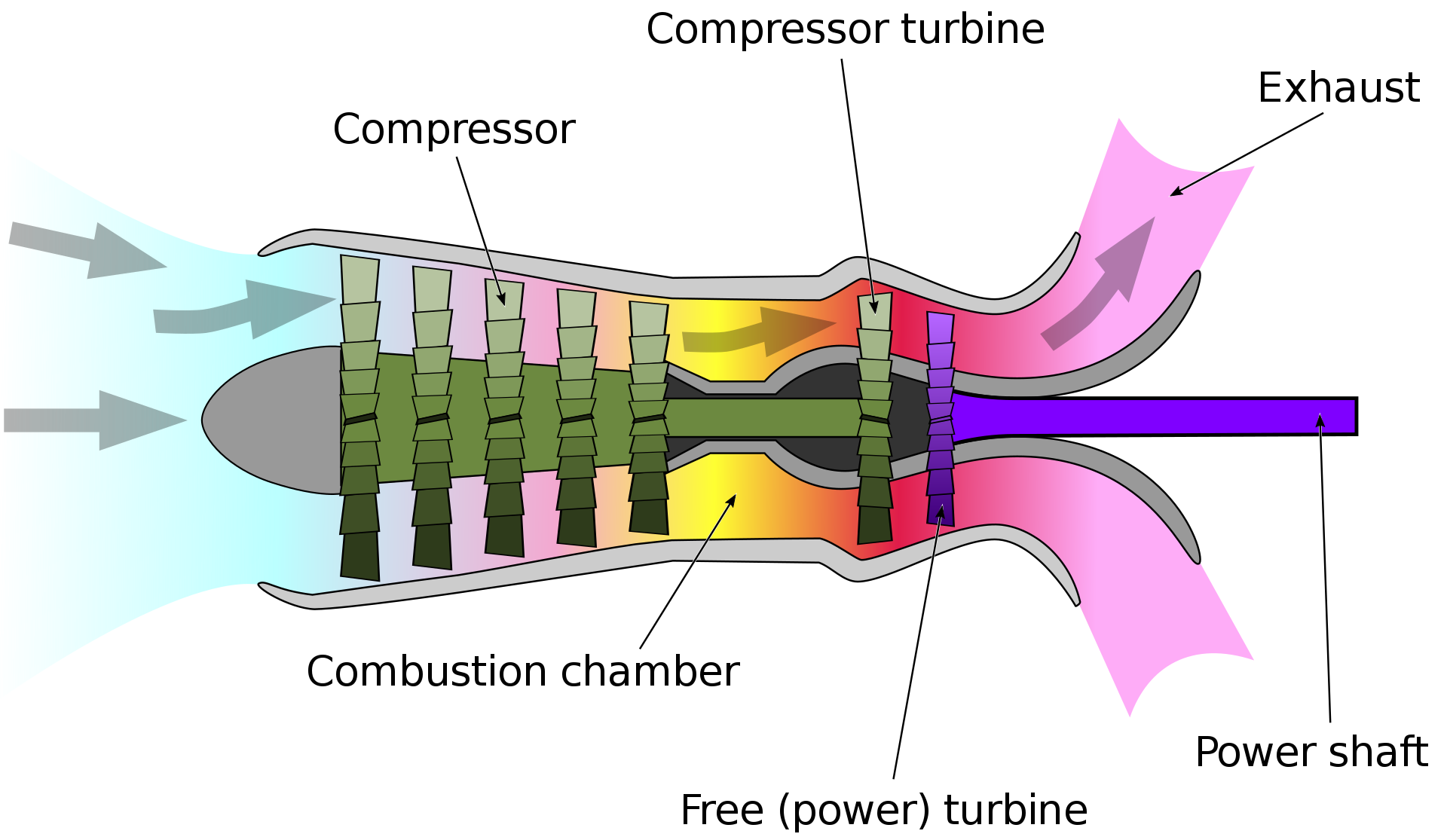
Turboshaft engines are commonly used in applications that require a sustained high-power output, high reliability, small size, and light weight. You will find this application in helicopters, auxiliary power units, boats and ships, tanks, hovercraft, and stationary equipment.
The Structure of the Blade
Blade and vanes have distinct functions but share similar geometrical elements. The vane redirects the flow path whilst the blade transfers the energy between gas and rotor. Blades must operate at high rotating speeds and temperatures, while vanes direct the stream propelled by the rotating blades to the next turbine stage with optimum efficiency. Both blades and vanes must be resistant to oxidation, corrosion, and wear, and provide longevity in service.
This is one the key aspects companies measure to improve their blades thereby improving the performance and extending the operational life of the blade or vane.
Measurement drives efficiency.
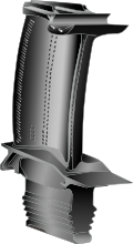
The structure and function of the blade/vane consists of three aspects:
1) The root mounts the blade to the rotor or casing. Roots could differ depending on the mechanical load, required mounting precision and manufacturing costs and we will revisit this subject in-depth in the future.
2) The airfoil which is functionally shaped to guarantee the correct interaction with the gas flow in the case of the vane is to redirect the flow path whereas the blade transfers the energy between gas and rotor. The airfoil transitions into the root and shroud via a transition radius and a curved platform surface.
The profile consists of a pressure and suction side with a leading and trailing edge that will be part of our in-depth blog.
3) The shroud is optional depending on the application of the turbine. Shrouded blades/vanes control and minimize leakage flow between blade tips and vanes as well as to limit vibration amplitudes to ensure the creation of a stabile outer ring.
WENZEL Measures #morepartsfaster
Blade manufacturing comes in a wide variety of shapes, dimensions, and requirements for every needed application out there. Profiles are designed to maximize the required output. No matter the size, surface area or lead time the CORE does not suffer limitations. The optical high speed scanning system was designed for the rough conditions of a direct production environment. CORE M is characterized by temperature stability, dirt, and vibration resistance. High dynamic linear drives and the robust base machine of the 6-axis-measuring-system allows measurements at high speed.
Quick point acquisition is ensured by the innovative optical high intensity light sensor made by WENZEL; on components difficult to access as well as on highly reflective surfaces; without time intensive re-positioning of the part or pretreatment of surfaces.
CORE M has a measurement volume of 500 mm x 500 mm x 2500 mm and is therefore ideal for the measurement of large components. Within the machine’s enclosure there is a system of dynamic balancing weights that counteract the forces generated by the high-speed movement of the scanner ensuring no loss of accuracy even at remarkably high measurement speeds. The comprehensive software package from WENZEL enables easy and fast evaluations on blades with blade analysis software developed in conjunction with industry partners.
As you might have realized by now we love measuring turbine blades with their gunmetal gray, and slick, gracious design. These small parts have the significant impact that enables us to explore the world through traveling, build our economies and protect our countries and loved ones are all good reasons why. I would encourage you to enjoy a relaxing river cruise on an old steamboat, marvel at the size of the tall wind turbines, visit Niagara Falls and think of how far we have come over the centuries. Remember that through measuring, improvements were made, and technology excelled. Stay tuned for Part 3 and our journey learning and measuring #allaboutblades.