CMM inspection of Turbine blades.
Most turbine blades are set up and dimensioned in a very traditional way suited to when they were inspected with guillotine style gages. Iterative alignments are complicated to say the least, not just best fitting 6 points in space but sometimes using mid-points or high point local scans to generate one of the best fitting points.
CMM’s have been used to do this inspection instead of dedicated gages in the last decades for a number of reasons;
- CMMs are flexible and, once programmed, can measure many different parts
- Maintenance, storage and calibration of one dedicated gage per part could be laborious and expensive
- Most importantly the industry demanded digital data for every measurement. GO/NOGO or subjective judgements in inspection have become unacceptable. Digital results can also be archived away easily for future reference if needed.
Those of us that have been in the business (measuring blades) for a while are aware of the problems of probing points on profiles such as blades and are very aware of phrases like “tip radius error” and “out of plane error”. CMM software vendors and CMM programmers have found elaborate work-arounds to compensate these know error conditions over the years, but as 3-axis or even 5-axis continuous contact scanning has become more the norm, then the work-arounds needed to become even more complex to cope with the amount of data produced and the fact that scanning probes have a habit of wandering “out of plane” when the actual surface is away from nominal.
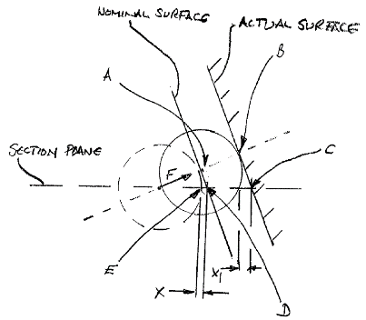
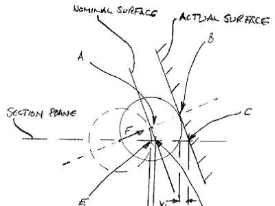
Please forgive my drawing,
It is many years since my drafting days were over! However, it will illustrate the issues.
Remember the profile is to be measured in section planes cut through the airfoil at various heights. The amount of twist and bend in blades produced today also compounds these effects.
The circle represent the CMM stylus ball and the point we really want to measure is Point C and then compare it to the nominal Point D.
Let’s keep it simple and imagine measuring this with a touch-trigger probe. We have 2 possible approaches;
- We can move in 2D and approach point D (from left to right), but instead of hitting point D we strike the surface earlier and actually record Point E, giving tip radius error of “X”. This effect can be lessened by using the smallest ball possible, but nevertheless it will still be there
- We approach the point along Vector F, but if the actual surface is away from nominal (as in this case), we overshoot and record point B, giving a tip radius error of “X1”. Actually we record Point A and apply the tip compensation in the direction of Vector F and record point B.
If you are scanning the section the similar effects occur. If the surface ‘wanders’ away from nominal, the scanning probe senses a drop in stylus force and vectors towards the surface to get back to its nominal stylus force. Without any further calculations or corrections the Z-axis value will drift, particularly with twisted and bent blade shapes.
As I mentioned previously, it is not beyond a skilled CMM programmer to apply some trigonometry calculations to his program to “approximate” Point C from the measured Point B.
With the Renishaw REVO 5-axis scanning solutions these problems and approximated solutions still occur, but other approaches become possible like sweep scanning.
Software programs developed for this approach program the collection of the sweep scan data (recording stylus ball center data to remove the tip radius error problem) and then intersect the point clouds collected with the section planes. The number of point ‘landing’ on the section plane exactly can be low and/or inconsistent. Software routines then process the point cloud further to push points close to the section plane onto the plane itself. This approach speeds up the process a lot and solves the problems associated with tip radius error and out of plane measurements, albeit with a fair amount of calculation and approximation.
This approach can also be adopted with laser scanners, but the surface reflectivity of the blade can determine the success or failure of the method. Even moderately shiny surfaces can cause issues (and measuring uncertainty) and spraying such parts with powder to fix the reflectivity problem, introduces another problem of powder thickness and consistency of powder thickness, again introducing an unpredictable uncertainty of measurement.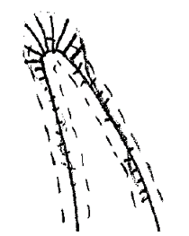
Another area of concern with contact CMM data is the errors generated when measuring the trailing edge (and for thin blades also the leading edge) of the blade. In this area the change in direction of the surface is rapid and particularly when the profile is a long way from nominal shape, the tip radius correction becomes erratic.
The error plot sketched on the right is very typical and most people associated with CMM report from turbines blades will be familiar with it.
This area of the blade is perhaps the hardest to manufacture to nominal, so it can be confusing with such reports to know whether this is a manufacturing error or a tip compensation error on the CMM.
 The methodology applied with 5-axis scanning on REVO described above does address this issue as well, within the constraints also described.
The sweep scanning methods also produces a massive amount of data describing the complete shape of the blade which can be incredibly useful to engineering, even if it is not giving the inspection group what they need without going through the sectioning process.
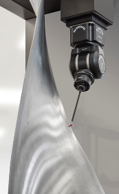
Here at WENZEL we have the same issues and work-arounds with our CMM solutions and we have to say that for many parts the CMM is the best solution, particularly when fitted with the REVO 5-axis scanning head. This is absolutely the best solution for blisks, multi-vane segment and large, heavy vanes.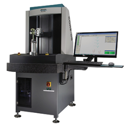
A Better Solution for Single blade measuring!
However, we believe we have a better solution for single blades – any blade from 1” tall to 80” tall fan blades. This solution is
a high speed optical scanning machine called CORE. The CORE machine is a 5 or 6 axis optical machine. The sensor, developed by WENZEL, projects a high intensity white spot onto the part. Then one or both cameras in the sensor detect the point of highest light intensity in the middle of the spot. The software then calculates the point position as with any other CMM. The key differences with CORE when compared with other optical systems is that it can operate on even highly polished surfaces and can cope with the finish of any turbine blade without spraying.
The CORE can also measure highly polished artefacts (like spheres and gage blocks) and so can run standard ISO 10360 tests for CMM verification. 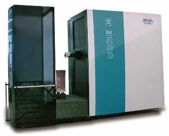
So whilst the CORE operates like a CMM in picking up the iterative alignment and scanning the profile sections, the key difference for CORE is that the sensor has effectively a zero tip radius and therefore none of the problems documented above occur.
CORE has the added benefits of being shop hardened, occupies a small footprint compared to traditional CMMS and measures blades in at least half the time of any other CMM.
So in conclusion, the inspection of turbine blades profiles have been measured with CMMs for many years and the inherent problems of “tip radius compensation” and “out of plane measurement” have been worked around. Sweep scanning systems go a long way to correcting these problems, but not without a fair amount of point manipulation and correction to report section scans with enough data.
If you need a machine that accurately measures and reports actual profiles without tip compensation errors and subsequent corrections, that can be certified to ISO standards like a traditional CMM and can measure today’s complex blade shapes way faster than any other measuring machine right out on the shop floor, then perhaps you should take a look at the CORE range from WENZEL.
For a more detailed comparison between bridge CMM and CORE please click here to read a blog from last year.
Andy Woodward
WENZEL America