How to measure turbine blades quick and easy
This is part 2 of Quartis where we will look at the advantages of measuring blades with this powerful software solution. Last week we touched on the basic features of Quartis and today we will look at how to measure turbine blades. A variety of the blade features can be measured with standard measuring applications but for those that cannot, WENZEL developed fully automated solutions like measuring, evaluating, and reporting strategies. This ensures easy and intuitive workflow with Quartis. We will focus on the CORE, since this 5-axis CMM was designed with turbine blades in mind. We will discuss the hybrid sensor system that can switch between high-speed optical and high-precision tactile measuring.
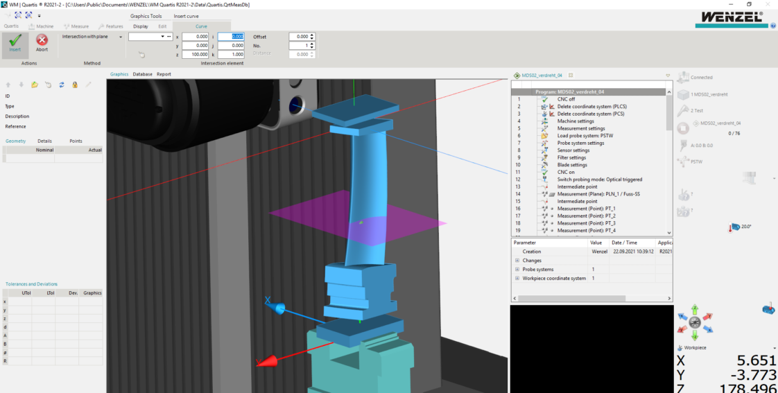
A closer look at WM Quartis
Quartis is extremely user-friendly. Measuring, evaluating, and reporting starts with the GUI (Graphical User Interface). We use the Microsoft user interface (Microsoft Fluent interface) following its guides and rules, menus, toolbars, bars, buttons etc. At the top you can find all the toolbars that you need for the Quartis functions, machine setup, measuring, and evaluating of those measured features. These toolbars are fixed and will always be visible.
In the middle of the screen, you can find your workplace with different windows to activate. These can be the graphics window, a database table, the program code, the reports section etc. All of them have separate toolbars that shows at the top when you work within these workplaces. On the left, there is an elements window that shows you the details of the element you clicked on. On the right, you can find the status of your machine, workpiece, measurement, probe, axis system, temperatures, etc.
Starting with your physical workpiece – the blade.
Every blade is different but all of them share significant detail. They are built and machined in reference to the longitudinal blade axis. Which mean we will use this feature to clamp our blade right in the middle of the rotary axis of the CORE. You can rely mostly on standard centric clamping vices, but occasionally with special root profiles (e.g. fire-tree), you will need to add blade-specific clamping jaws. No matter what, once clammed, the blade axis and the rotary axis are parallel, the rotary table will ensure you measure and reach each geometrical element with ease.
Clamping can be done manually, automated (pressured air) or even fully automated with robots that load your CORE.
How do you set up your blade measurement?
After clamping the blade, you can open Quartis and start working in the toolbar from left to right. Using the Quartis bar (create, open, save, import, export, settings) you start by loading your blade CAD-model. The axis system of the CAD model (usually the middle of the turbine) gets arranged on top of the machine axis system. The physical placement of the blade inside the CORE and the arrangement inside Quartis usually differ since the blade gets arranged via the global CAD-turbine axis system. You can fit your blade easily with some of the internal fitting options that Quartis offers. You could also load more CAD models in the case of special clamping devices. This is necessary for collision control during the measurement process.
The Machine bar is used for your measurement set up: speed, search distances etc. In addition, you can also calibrate your probe system and your rotary axis of the CORE. These are automated procedures that need no further action other than just clicking “start calibration.” Remember to do this regularly to avoid any incorrect measurements.
How do you measure a blade?
In the Measuring bar we see all the functionalities we need to do the measuring, construct, and align the workpiece – our blade. A first vague alignment can be done by manually probing easily recognizable surfaces and points. You should use areas that are used for the blade assembly (especially root surfaces) to increase positioning accuracy. Now your physical placement of the blade inside the CORE and the arrangement inside Quartis are on point. Everything is set up to start the fully automated precise alignment and measurement. By fully automated we mean that there is no more manual probing of the workpiece.
From now on you only work in Quartis, plan your next steps and everything will be performed in real-time by the CORE.
For the precise alignment of your blade, you need to take the assembly geometries (usually root geometries) and the drawing into consideration. The best way is to track the blade axis and align your workpiece along this axis. You can do that by measuring the root profiles on both sides and creating the symmetric plane “A” in-between. For the root-profile-limiting surfaces, it depends on the assembly method. If the blade is assembled in a symmetric way you can repeat this process, if it is assembled via a side contact you should find a value on your drawing that shows the distance of your axis to that side surface. In both cases, you get a second plane “B” in the middle of the blade. Now you can intersect plane “A” and “B” with a Quartis design function and you get your blade axis right in the middle of the blade. In combination with two other points to lock the rotation around this axis and a third point to lock the blade in height, you got all your elements to precisely align the blade within Quartis and perfectly match the physical blade on the CORE. Different alignment functions are available to achieve this desired final state.
After aligning your blade, you can start the automated measuring. You simply choose your element (plane, point, circle, cylinder, curve, etc.) in the measuring bar, click onto the CAD model, check your measurement settings, confirm, and the measurement (e.g., measuring strategy, filters, additional safety paths, etc.) will be performed in real-time in Quartis and physically on the machine. None of these functions is blade-specific since Quartis offers all the measurement functionalities that you need for your blade measurement, starting from points and planes to complex curves.
The measurement of the airfoil is especially easy. You take the drawing that shows you the height of airfoil profiles to measure. You simply design these profiles by intersecting the airfoil surface with an intersection plane and as a result, you get your profile. Then you can simply click on curve measurement, choose the profile and the CORE starts measuring. Easy-peasy!
The CORE starts measuring the profile and, in the case, where the blade needs to turn around its blade axis a lot, the required rotational movements of the CORE will be performed automatically to align the sensor in the best way to achieve the ultimate measuring performance. This is where the power of 5-axis simultaneous measurement shines. For optimal efficiency, you can use the high-speed scanning mode on the optical sensor. You do not want to miss our video next week where we will show you how this works.
Advanced settings for blade recognition, sensor performance, and 5-axis settings can be adjusted if needed. All these features will be discussed in a future blog post.
How do you evaluate your blade measurements?
In the next tool bar, the Features bar, we find all the features we can evaluate. You simply choose a feature (straightness, symmetry, position, profile tolerance etc.), decide on your measuring element and the evaluation is done. Advanced settings to evaluate specific features are also available here.
For blade profiles you get the option to assess them with the Blade Analyzer. Here the key features of a turbine blade profile (leading and trailing edge radius, profile tolerance, required profile fitting as feedback for the manufacturing process, etc.) are evaluated automatically and written into a report. More about this special software solution in our future posts.
How do you organize all your data in a blade report?
To find the Report bar, you must switch from the graphical workplace to the report workplace. Here you can create a new report, you can choose a blank page or a tailored template depending on your company’s preferences. Now you simply choose a picture for your blade, the elements that you want to include within your report, and everything will be aligned within the report automatically. You can save the report as Quartis reports, pdf, text or csv-file.
How to automate?
All these steps can be tracked by the program manager that automatically saves each step of your work and saves it as a “step list.” The next time you want to measure the same part you simply load your program; press start and every step will be done in the same way. No manual programming or code-writing is needed.