Previously we looked at the turbine that produces continuous power by fast-moving water, steam, gas wind, or other fluid. This week in #allaboutblades we will look at the blade/vane that is fitted to the wheel or rotor and how it is assembled. The shape and construction of the root, shroud and airfoil of the blade are determined by its application (steam turbines, gas turbines, compressor), but in essence they all function the same.
The shape of the blade is determined by the *thermal and mechanical boundary conditions which can vary a lot depending on the environment it functions and the application.
The Load has a Heavy Impact
The load that the blade would endure determines the design too. *Static loads in the form of centrifugal forces as well as torque and bending forces (in the form of air resistance) as well as dynamic loads of the moving blades.
Other factors like blade elongation (due to heat), hot temperatures, erosion, corrosion, and oxidation will determine the design too.
influences on the design process
First, everything is designed to make sure that the product is in spec but manufactured in the most cost-effective way with minimal waste and maximum performance. The root, shroud and airfoil design depend on the environmental conditions the blade will need to perform in.
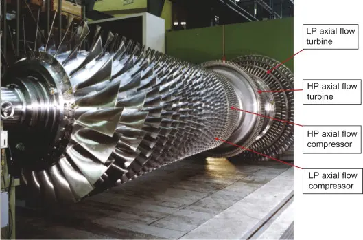
High, intermediate, or low-pressure applications determine the blade size and material choice. For example, with high-pressure turbines, the blades tend to be smaller, due to an environment of high heat and pressure. It also needs heat-resistant materials like nickel-based alloys. While with low-pressure turbines with lower temperatures the blades tend to be exceptionally long and made from less heat resistant materials like common stainless turbine steel. But with their high mechanical loads high mass of blades at high turning speeds lead to high centrifugal forces and mechanical loads, which leads to more complex roots that is imperative for safety reasons.
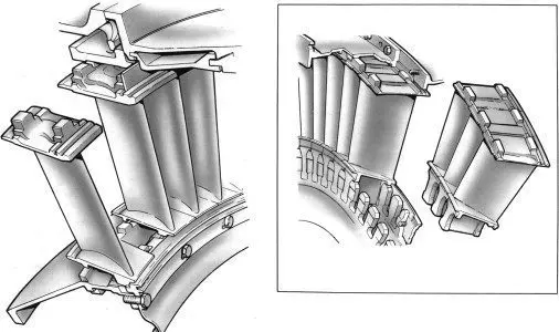
3 Main Parts: Root, shroud, and airfoil
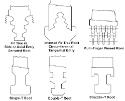
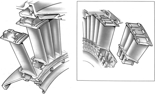
The Root mounts the blade to the rotor or in the case of a vane it will be mounted into the casing. By mounting the blades/vanes next to each other a big “circle” of blades/vanes is created fully and interact with the gas passing through the turbine or compressor. The shape of the root depends on the thermal and mechanical load it will need to withstand over periods of time. The design engineers must keep manufacturing costs down but at the same time enhance performance. A more complicated root design means a higher safety rating due to more “shoulders” taking the load but that will mean higher manufacturing costs because the root’s shape requires higher precision and tools and techniques in the manufacturing process.
The connection of the blade/vane to the rotor/casing is usually created via a form fit or via a welded connection.
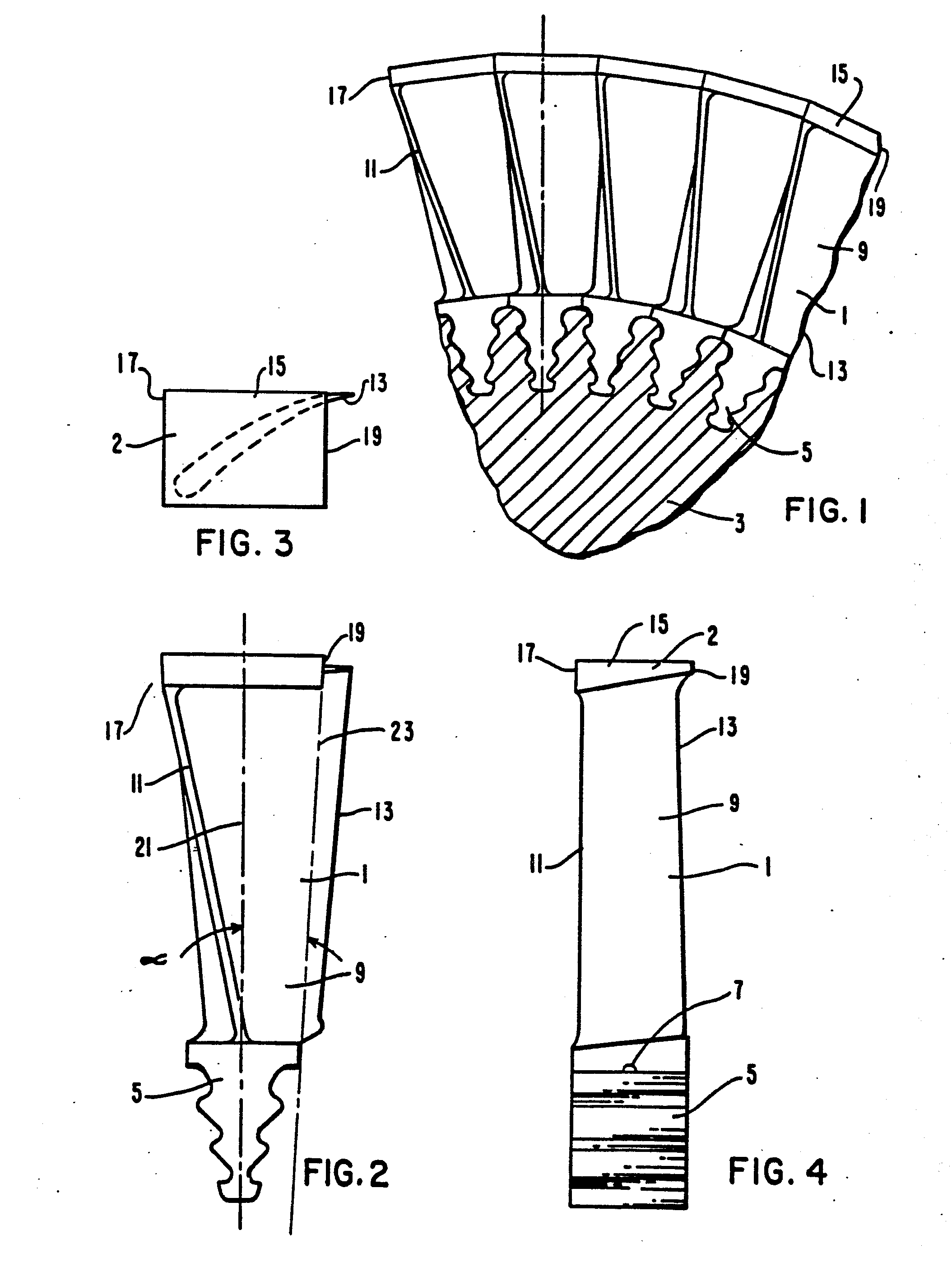

The Shroud’s main purpose is to stabilize the blades/vanes via a loose connection between the neighboring shrouds. After assembly this closed ring of shrouds lowers the flow leakage of the gas or air that is bypassing the airfoil. Additionally, on the top of the shroud there can be a labyrinth design to further decrease leakage. To increase stability between the shrouds they can be connected to each other with interlocking geometrical features.
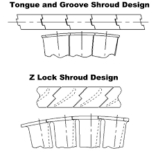
When stabilizing and leakage are not a factor in the performance above features are not necessary.
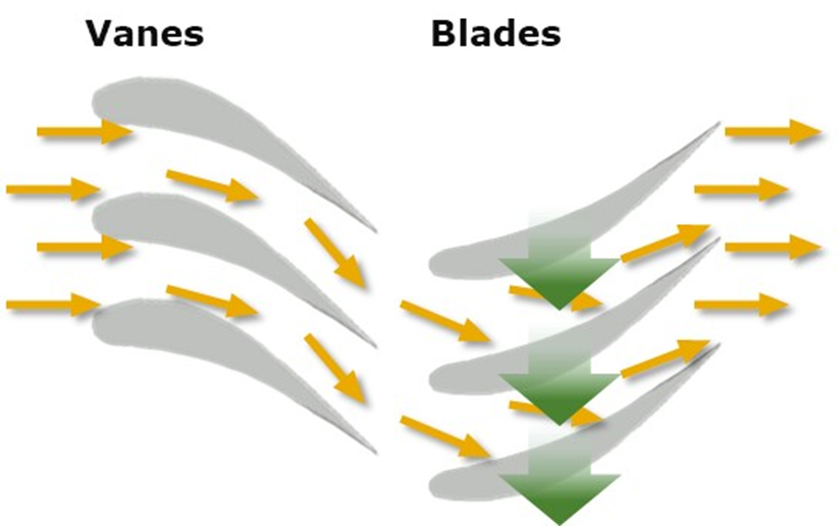
The Airfoil is the part that interacts with the gas or steam or fluid passing by. In the case of a turbine blade its function is to convert the energy of the bypassing gas into a rotation of the rotor. In the case of a compressor blade the forced rotation of the rotor (via an engine) leads to air being sucked in and compressed by the airfoils of multiple stages. Therefore, the compressor works with a reserved principle.
The function of a vane’s airfoil (turbine or compressor) is to redirect the flow of the gas at the perfect angle to interact with the next blade. This is important for optimal performance and making maximum use of the gas. Both blades and vane’s airfoil profiles show a leading-edge, trailing edge which is a, suction side, and pressure side. The leading edge is where the gas flow enters the profile while the trailing edge is where the gas leaves the profile. These neighboring blades build up the channel of gas flow that pass over the profiles and performs in the way it was designed to.
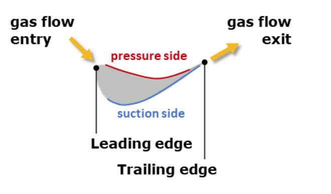
An airfoil profile is curved from the leading to trailing edge to ensure the flow enters the profile in a certain direction and gets redirected within the channel to interact in the desired way and leaves the profile in another direction. The entrance and exit angles of the airfoil profiles must be synchronized with the gas flow directions to be as efficient as possible. The suction and pressure side in-between have to be designed as smoothly and homogeneously as possible to match the high-efficiency requirements.
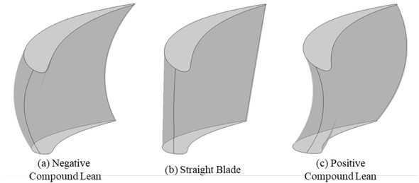
The profiles of the airfoil change constantly from the root to the shroud depending on the local boundary conditions (especially flow speeds). This results in a continuous change of airfoil shape and lean and twist from root to shroud.
The concrete radii, shapes, lengths, and thicknesses of a blade are determined via complex simulation software that calculates speeds, temperatures, pressures, and reducing imperfections in the areas where they must perform optimally.
These geometrical elements must be designed, manufactured, and measured on high-performance levels to match the highest grades of efficiency as well as for future improvements. Measurement plays an intricate part in determining what is the best performing design and where to improve what.

How to measure
Quality control and quality assurance are a big part of ensuring safety. In conclusion we will look at measuring the blade with WENZEL’s Core machine which was developed to measure more parts faster. Especially in aviation where the blades have an extremely narrow leading edge. The spot of light from the Core can measure the smallest of radii and pick up the smallest of defects. This is true in medical device manufacturing too, which is known for their intricate and complicated parts.
Unlike other optical systems, the CORE can measure recently machined, polished, and even mirror-finished parts without the need to spray them white. The fully integrated optical sensors provide the dexterity and measurement capability needed to rapidly inspect the complex geometry of today`s parts. CORE’s focus is measurements on the manufacturing floor. The CORE construction has been FEM optimized. Linear Guide-Ways with wide bearing spreads ensure long-life and stable operation even in the production environments from 18° – 30°C.
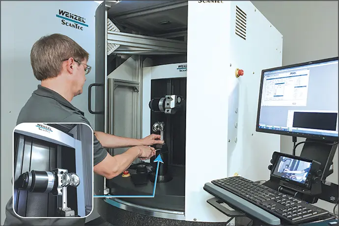
An integral, high resolution, direct drive Rotary Table provides synchronous part positioning to the measuring sensor further optimizing inspection cycle through a complete simultaneous 5 axis motion. Maximum scanning speed is up to 400 mm/s across the surface of the part. CORE has a travel range of 300 x 200 x 450 mm and is optimized for measurement of turbine blades, orthopedic implants, and other small high-volume quality critical manufactured parts
Measuring more parts faster is what WENZEL CMM’s do best!
*Static and dynamic weight: When you walk towards your parked car it is a static weight in front of the grocery store but when you get in and start driving the car it is an example of dynamic weight on the road.
*Thermal and Mechanical boundary: It is the thermal and mechanical environment it functions in. Operating temperatures, temperature Changes, pressure, forces, torques, etc.
Thank you for following our #allaboutblade series and do not hesitate to contact us for any questions you might have. We would love to hear from you with any feedback on our series too, feel free to contact us at sales@wenzelamerica.com
DON’T MISS OUT
WENZEL will be at various Expos this Autumn be on the look out for us and come and say hi.
Follow us on LinkedIn, Instagram or subscribe to our monthly Newsletter to stay up to date with all metrology news.


![]()