AUKOM Training explained

AUKOM Training explain

It’s not obvious from the name what AUKOM training is so this blog is meant to explain.

WENZEL offers software training and training for the use of our coordinate measuring machines. Our application engineers specifically provide software training in the use of OpenDMIS and WM|Quartis online or onsite.

This is not all, WENZEL America offers training in Metrology in a generic sense too, not specific to any software but applicable to all software or ensuring methods. Today we look at exactly what the various stages of AUKOM training consist of. AUKOM is more than a common metrology language that will ensure effective communication across departments. It is a global training standard for production coordinate measurement practices which is vendor neutral. This means that the skills gained, and procedures learned during this certified training can be applied using any brand of measuring equipment and software. Here are the various stages of training in an easy-to-read menu form.

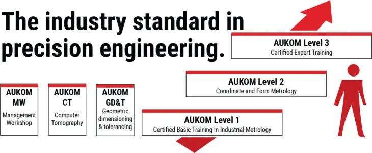
The various stages of AUKOM training in a menu form:

WENZEL is a member of ‚Ausbildung Koordinatenmesstechnik e. V. (AUKOM) and one of the leading providers of AUKOM training in North America. The association promotes basic training in the field of industrial production metrology, in particular coordinate measuring. AUKOM ensures the standards and comparability of the courses offered by the members in the context of coordinate metrology training. By teaching a consistent methodology, AUKOM sets you and your team up to be on the same page which assist in execution between the engineering department to the metrology lab. The program consists of three levels and a certificate is provided for each upon passing the course exam.
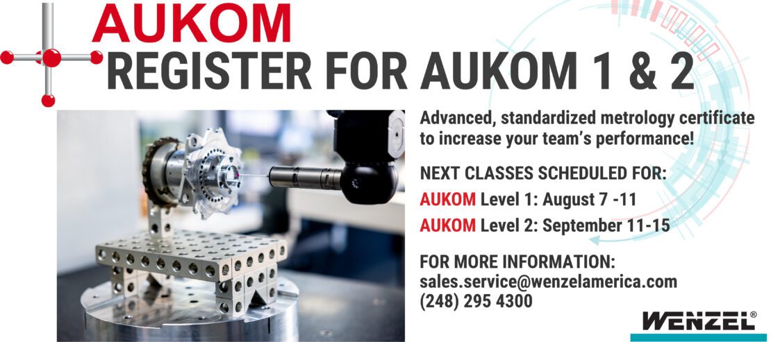
AUKOM levels of training. Generic metrology training.

AUKOM Level 1

1-1 Units

SI Units, incl. Definition and History, Base Quantities, Derived Quantities, Prefixes of Units, Angles, Conversion Degrees <-> Radian, Conventional Measuring and Test Equipment

1-2 Coordinate Systems

(Mathematical) Drawing Plane, Origin, Cartesian Coordinates, Right-Hand Rule, Translation and Rotation, Polar Coordinates, Cylindrical and Spherical Coordinate System

1-3 Coordinate Measuring Machines

History of Coordinate measuring machines, Cantilever/Bridge/Column/Gantry Types, Differences in the Types, Axis Guide, Measuring Computer and Software, Work Holding Fixture, Accuracy of Coordinate Measuring Machines, CAA Correction, Form Measuring Machines

1-4 Sensors

Sensor selection, Stylus System, Stylus, optical sensors, Image Processing, Laser Triangulation

1-5 Basic definitions

Drawing Entries (Dimensions, Tolerance Symbols), Standard Reference, Differences Nominal Element – Real Element – Extracted Element – Associated Element, Free Form surfaces

1-6 Dimensional Tolerance

Dimensional Tolerances, Taylor’s Principle, Standards, Symbols and Drawing Entries, Length Dimensions, Angular Dimensions, Limiting Dimensions and Fits, ISO Fitting/Mating System, Common Tolerances

1-7 Geometric elements

Standard form elements: Plane/ Cylinder/ Cone/ Sphere/ Line/ Circle/ Point/ Ellipse, Vector, Normal Vector, Minimum Number of Points, Projection

1-8 Geometric constructions

Calculation of characteristics out of two geometrical features (distance, angle), Calculation of features out of two geometrical features (Intersection, Symmetry), Calculation of new features out of some geometrical features (Construction)

1-9 Preparing a Measurement on the Coordinate Measuring Machine

Standardized Temperature, Part Cleaning, Temperature Control, Fixturing, (Avoiding Distortion), Fixturing Systems, CMM and Software Startup

1-10 Stylus Selection and Qualification

Stylus System Selection, Stylus Qualification, Reference Sphere, Reference Stylus, Stylus Sphere Radius Correction, Stylus Tip Bending Correction, Mechanical Filter Effect of the Stylus, Errors of Incorrect Qualification,

1-11 Measuring using Coordinate Measuring Machines

Determining part Coordinate System, Difference to Control Coordinate System, Manual and automatic Alignment, Probing, References, Consequences of Collisions, Number of Probing Points and their Distribution, Influences on measuring result

1-12 Evaluation of Measurement and Statistics

Importance of Statistical Parameters, Outliers, Scattering, Histogram Representation, Compensation Methods, Influences on measuring result

1-13 Inspection planning

Completely defined characteristic, Purpose of the Measurement, Production of workpiece, Function of workpiece, Feature description, Manufacturing Methods and Accuracies, Shape Deviations, Uncertainty Effects, Awareness of Measuring Uncertainty, Inspection planning, Identifying measuring features

1-14 Documentation and Quality Management

Measurement Reports, Quality Control Charts, Cooperation between Design – Production – Testing, Reproducible and Clear Measurement Documentation, Measuring Strategy documentation

AUKOM Training explain

AUKOM Training explain

aukom training with WENZEL cmm experts.

AUKOM Level 2

2-1 Overview of the Entire Measuring Process

Short repetition of the contents of stage 1

2-2 Geometric Overview

Standard Geometric Elements, Surface and Space Points, Punched Hole/Slot, Tetragonal/Hexagonal Hole, Symmetry, Perpendicular, Parallelism, Angle in Space, Coordinate System Transformations

2-3 Form and Positional Tolerances

Introduction to the Form and Positional Tolerances, Symbols and Drawing Entries, Form Tolerances, Reference Designation, Directional, Positional and Runout Tolerances, General Tolerances

2-4 Measuring Strategy

Define Clamping Setups and References (Practical Instructions), Order of Reference and Origin Selection, Iterative Alignment, Alignment According to the 3-2-1 and Best-Fit Methods (3-D Fit), Measuring Element and Auxiliary Elements, Machine Grid Measurements, Contour Measurements, Measurement with Cylinder Surfaces, etc.

2-5 Probing Strategy – Tactile

Number and Distribution of Probing Points, Probing Force and Speed, incl. Material Properties, Stylus Diameter, Special Styli, Scanning

2-6 Probing Strategy – Image Processing

Single-shot measurement, Multi-shot measurement, Edge finder, Contour image processing, Projection optics, Illumination, Filter, Scanning, Auto focus

2-7 Probing Strategy – Distance Sensors

Laser triangulation sensors, Foucault sensor, White light sensor, Light section sensor, Photogrammetry, Fringe protection, Influence on the measuring results

2-8 CNC Programming

Teach-In, Offline Programming, Measuring against CAD Data, Clarity and Self-Explanatoriness of Variables, Modules and Programs

2-9 Measurement of Free Form Surfaces

Element types in Free Form Surface Metrology,? Effect of a 3D-Fit, Different Measuring Strategies, Programming Methods for Establishing Measurement Sequences

2-10 Evaluation

Evaluation Criteria: Function-oriented and Manufacturing-oriented Evaluation Methods, Differences in the Association Methods (Gauss, Envelope, Minimum Requirement), Constructions, Graphic and Tabular Evaluation, Measurement Logs

2-11 Effects on the Measurement Result

Effects on the Measurement Result, Reduction of Measurement Uncertainty, Detection and Reduction of Systematic and Random Effects, Temperature Compensation

2-12 Documentation

Principles of Documented and Reproducible Documentation, Graphic Evaluation, Form Plots, Measurement Reports and Their Improvement

2-13 Test Equipment Monitoring

Test Equipment Monitoring, incl. Monitoring Strategies, Test Specimen, normals, Monitoring and Acceptance Test of Coordinate Measuring Machines, Qualification Chain

2-14 Good Measurement Practice

Good Measurement Practice, Necessity of Cooperation

AUKOM Level 3

3-1 Basic Knowledge – Geometry

Calculation of Angle, Center of Gravity, Distance, Area

3-2 Basic Knowledge – Production Technology

Production Types and Achievable Production Precisions, Shape Deviations and Their Causes, Functionally Adequate Design and Construction Suitable for Production

3-3 Basic Knowledge – CAD

Principles of Construction and Technical Drawing, Principles and Tools of CAD Design, Imaging of Geometry, Model Types, CAD Data Dimensions, CAD Formats, Import of CAD Data, Interfaces

3-4 Point Cloud and Computer Tomography

Development of computer tomography technology, Physical principle, From the radiographic image to the measure, Tomography “on the image”, Region of interest, Initial sampling of the entire component , Evaluations of the deviations from the nominal geometry, Measurement of sections, Checking the material structure, Radiation spectrum, Beam hardening, Scattered radiation, Cone beam artifact, Noise, Further applications; Additionally: Fringe Projection, Photogrammetry, Tracking

3-5 Creation of Measurement Programs

Precision-Optimized Measuring Sequence, Time-Optimized Measuring Sequence, Travel Path Optimization, Feature-Oriented Measuring, Remote Programming, Safety Points and Planes, Program Loops / Branches/ Modules, Macros, User Interfaces, Program Optimization Loops, If/Then Conditions, DMIS Standard

3-6 Digital Filtering and Evaluation

Software Filters, Gauss Filters, High-Pass, Low-Pass, Waviness, Roughness, Comparison Form Tester – CMM

3-7 Monitoring of CMMs

CMM Monitoring, ISO 10360/VDI 2617, Possibilities to optimize the accuracy of CMMs, Examples, Experience

3-8 Measuring Uncertainty and Measuring Process Suitability

GUM Handbook, Determination of the Measuring Uncertainty, Uncertainty Budgets, PUMA Method, Increasing Measurement Uncertainty, Extended Measurement Uncertainty, Conformity, ISO 14253, Determination of Uncertainty Using Calibrated parts, Use of the Virtual CMM, Measuring Process Suitability according to MSA (GR&R), VDA 5, Comparing the methods

3-9 Quality Management

Quality Management Systems, Quality Management Handbooks, Quality Management Standards, Audit and Certification, Quality Tools, Fixed and Actual Costs, Origin of Errors and Error Elimination, Cost-Conscious Tolerance

3-10 Process Monitoring

Process Monitoring, Statistical Process Control (SPC), cp Values, cpk Values, cm Values, cmk Values, Monitoring Strategies and Quality Control Cards

3-11 Aspects of Measuring Room Management

Measured Data Management, Measuring Room Management, User Qualification, Training Plans and Options for Metrologists

AUKOM GD&T

GD&T-1 Basic rules of the ISO system of GPS-System
Introduction, ISO 8015 – Basic rules of the Geometrical Product Specification (GPS), Steps to check geometrical deviations, extracted median line – extracted median surface

GD&T-2 Tolerances of form, orientation, location and run-out – drawing indications 
Drawing symbols to indicate form, orientation, location and run-out tolerances, Tolerance zones, Default rules of indications and examples to indicate exceptions

GD&T-3 Tolerances of form
Straightness, Roundness, Flatness, Cylindricity, Measuring of form deviations

GD&T-4 Tolerances of orientation, location and run-out
Relation between form deviations and orientation, location, run-out deviations, Datum referencing, Orientation, Location, Run-out

GD&T-5 Tolerances of profile form

Definitions, Drawing indications, Examples

GD&T-6 Principles of tolerancing I 
Definition of sizes – ISO and ASME, Principle of independence, Envelope requirement, Summary and examples

GD&T-7 Principles of tolerancing II 

Basic rules of drawing indication, MMR – Maximum Material Requirement, Tolerancing of form and perpendicular deviations using MMR, Tolerancing of positional deviations using MMR, Checking workpieces considering MMR, Tolerancing of coaxial deviations using MMR, Tolerancing of symmetry deviations using MMR, LMR – Least Material Requirement, Reciprocity requirement

GD&T-8 Tolerances of form, orientation, location and run-out – ASME 
Basic rules and definitions, Envelope requirement, Datum referencing, Form tolerances, Orientation tolerances, Location tolerances, Composite and multiple-single-segment position tolerances, Profile form tolerances

GD&T-9 Workshop
Overview about the use of association criteria (Default rules) , Additional tolerancing indications in future (Deviations of the default rules), Examples to filtering, straightness tolerancing and datum referencing, Positional tolerancing (Without and with maximum material requirement), Symmetry tolerancing (Maximum material requirement), Maximum material requirement – Simulation of Go-gauging, Maximum material requirement – Comparison of optimization criteria.

REGISTER FOR AUKOM TRAINING for this fall

I hope this outline helps give you an idea of some of the material we have to offer here at WENZEL that will benefit your manufacturing process. Should you have more questions about our training programs or want to register for AUKOM training coming up in August and September of 2023, please don’t hesitate to contact us at [email protected]. We offer online, onsite and classroom-style training. Make 2023 the year to invest in your team.

Follow us on LinkedIn and be in the know of all the latest news or visit our website at www.wenzelamerica.com.